Page 1 of 1
0B15
Posted: Mon Jan 16, 2017 5:16 pm
by AlanOB15
I just bought the plans for this boat and its my first. I did think I was going to use the stitch and glue method and did not think I needed to build a gig or frame. Has anyone built this boat in that way?

Thanks in advance
Alan
Re: 0B15
Posted: Mon Jan 16, 2017 5:51 pm
by jacquesmm
You don't need a jig but you have to bend the hull panels around the frames, that is stitch and glue.
Re: 0B15
Posted: Tue Jan 17, 2017 7:02 am
by AlanOB15
Thanks. So in the tutorials section there is a list of build methods "Hull Assembly Methods Overview" and one of the listed ones is Molds (=frames) and stringers interlock and automatically correct possible alignment mistakes. Very little bracing or leveling is required and the assembly progresses very fast. (See detailed description of this method in a separate tutorial)
Anyone know where is separate tutorial is located?
I have looked at all of the builds and I dont see this one.
Alan
Re: 0B15
Posted: Tue Jan 17, 2017 7:58 am
by silentneko
Think this is what you are looking for. It does call it a jig, but it's not a complicated one where accuracy is needed like on a strip built boat.
http://bateau2.com/howto/jig.php
Re: 0B15
Posted: Tue Jan 17, 2017 8:32 am
by AlanOB15
Thanks silentneko. I was actually hoping to build without a Jig if I could and there is mention of using molds without one. IN the build section and reference to see other tutorial but I dont see that one. Has anyone build this boat or similar just using the molds/frames to correct the shape.
Re: 0B15
Posted: Tue Jan 17, 2017 8:45 am
by AlanOB15
More specifically why cant I build it like this one
http://baysidewoodenboats.com.au/galleries/fleet/ where the bulkheads/molds/frames are what makes the boat straight.
Re: 0B15
Posted: Tue Jan 17, 2017 10:02 am
by jacquesmm
There seem to be confusion about the definition of stitch and glue. Stitch and glue means a hull made from panels assembled with stitches then taped with epoxy. Jig or not, the OB15 is always a stitch and glue boat.
The OB15 plans and building notes show how to build the boat. The plans show a drawing of the jig and the notes explain step by step how to assemble the hull on a jig.
Small boats for rowing or sail are often built without a jig using the folding panel method. It is the method we show for our small boats like the PK78.
It is difficult to obtain a perfectly symmetrical and balanced hull with that method but this does not matter for rowing or sailing small boats.
It matters very much for a planing hull. A small difference in hull shape will affect performance. If you build the OB15 hull with the folding panel method, you may end up with a boat that constantly lean or heel to one side, pulls to one side or even does not get on plane easily.
For that reason, I specify building on a jig for all planing boats.
Hundreds of OB15 were built that way and they work perfectly well.
The boat you reference too is a small row boat that can take an engine. I have seen that boat, it's nice but not a planing boat. The bulkheads do not guarantee a straight boat, it can end up like twisted banana.

Knowing all that, the decision is up to you. You can build the OB15 with the folding panels method, the plans show the dimensions for the panels. It is not easier and there is a risk to end up with a twisted hull.
Re: 0B15
Posted: Tue Jan 17, 2017 12:55 pm
by AlanOB15
Thanks for the detailed response. That's what I did not understand, there there was a risk in using that build method on that boat. I'll build the Jig

Thanks
Alan
Re: 0B15
Posted: Tue Jan 17, 2017 3:29 pm
by jacquesmm
Good decision.
The OB15's are good boats. One of my neighbors build one 20 years ago and still uses it every week-end.
Re: 0B15 Jig Mold Help!!
Posted: Mon Jan 23, 2017 9:27 am
by AlanOB15
Cant quite figure our the placement of model on the Jig from the plans. All the molds are of different heights right, so should I align them from the top so they are all the same height or from the bottom so that the highs are different.
Thanks in advance
Alan
Re: 0B15
Posted: Mon Jan 23, 2017 10:32 am
by pee wee
Hi Alan, I don't have the OB15 plans, but JM normally designates a base line to measure up and down from when cutting out the parts, and that is what should be in a line, not the tops or bottoms of the molds. Take a look at the plans and see if you don't identify it.
Re: 0B15
Posted: Mon Jan 23, 2017 10:52 am
by AlanOB15
Thanks I do see a line (BL) that must be the base line. Is it ok to publish a screen shot of the jig plan do you know?
Re: 0B15
Posted: Mon Jan 23, 2017 11:04 am
by jacquesmm
The baseline is the base for your alignments.
See this:

Complete explanations here:
http://bateau2.com/howto/jig.php
If that is not clear, post the question.
Re: 0B15
Posted: Mon Jan 23, 2017 11:30 am
by AlanOB15
So I see a baseline and I'm assuming in this case that is from the strong-back level and I see a measurement of 748mm from the baseline to the top of the trasnsom plus molds 3 & 4 and that measurement is longer than the height of those molds so I need to raise them I guess so that the top is 748mm from the baseline. What I do not see is a height for the bow or molds plus 1 & 2. I can see that the bow mold sits on the base line but the vertical height of molds 1 & 2 are a mystery to me right now.
I have read what you sent on and thanks but I just don't see that on the plans and maybe Im reading it wrong because every time I look I see more info I did not see before.
Alan
Re: 0B15
Posted: Mon Jan 23, 2017 12:32 pm
by jacquesmm
You put the baseline at the level you want but for a 1st boat, keep it simple and use the dimensions I show.
Follow the tutorial that I linked to in the previous post:
- set up strongbacks
- cut your molds as shown on the plans
- put your molds on the strongbacks
- line them up vertically using the top of the strongbacks as the baseline.
If that is not clear, please read the tutorial. The OB15 does not use stringers but the set up of the molds is always done the same way, stringers or not.
If you want, we can set up a first mold, for example mold #3.
Let's work on one mold only and use this check list:
- are you strong backs level and set up like on the OB15 plans?
- is mold # 3 cut and CL marked?
- did your mark the longitudinal location of mold # 3 on the strongbacks
- do you have short 2x4 pieces cut and ready to raise the mold to the correct level?
If yes to all the above:
- clamp your 2x4 braces to the marked location
- clamp mold # 3 to the 2x4's
- adjust the level to match the level of the baseline that I show on the plans.
That's all there is to it. It is almost faster to do it than to try to describe but please, look through our gallery, there are many pictures of that method.
Here isa good web page about setting up the strongbacks:
http://bateau2.com/howto/foam3.php
Here is a picture of a mold on the strongbacks:
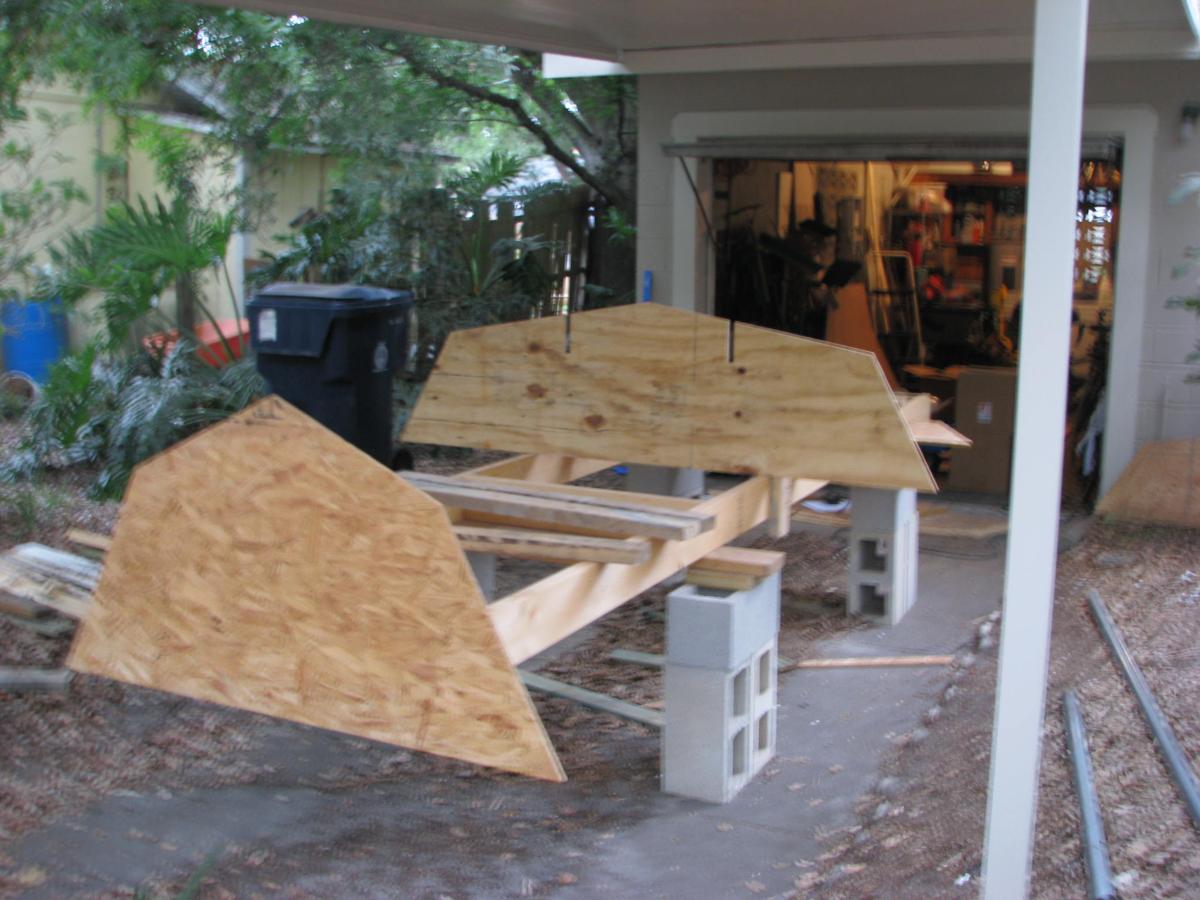
another one:
You don't have the stringers in the OB15 but same method for the molds.
Re: 0B15
Posted: Mon Jan 23, 2017 12:56 pm
by AlanOB15
Note to self> Look harder at the plans. I found the BL on the actual mold measurements. Thanks for the help but unfortunately it may not be the last
Alan
Re: 0B15
Posted: Mon Jan 23, 2017 1:23 pm
by pee wee
AlanOB15 wrote: ↑Mon Jan 23, 2017 12:56 pm
Note to self> Look harder at the plans. I found the BL on the actual mold measurements. Thanks for the help but unfortunately it may not be the last
Alan
It's not easy to describe in a two dimensional plan all the dimensions of a shape like a boat with all its details, so the specifics get spread across several pages. You'll find yourself needing to flip back and forth between pages to get the whole picture, and it's common for a first time builder to miss things and think critical information got left out. Usually a careful reexamination of the plans will provide the answer.
Re: 0B15
Posted: Mon Jan 23, 2017 1:37 pm
by jacquesmm
It will be muhc easier on the second boat
Re: 0B15
Posted: Mon Jan 23, 2017 3:37 pm
by AlanOB15
Again,, thanks guys for all the help!
Alan
Re: 0B15
Posted: Tue Jan 24, 2017 2:20 am
by danieloldhouse
jacquesmm wrote: ↑Mon Jan 23, 2017 1:37 pm
It will be muhc easier on the second boat
Usually perfection is reached on the third
Re: 0B15
Posted: Wed Jan 25, 2017 11:02 am
by AlanOB15
Okay, This time I have looked before posting!! Is there on indication on the plans of the amount of overlap there should be on the top and bottom panels. There is a visible line on the drawing on the bottom panels but I dont see a measurement.
Thanks
Alan
Re: 0B15
Posted: Thu Jan 26, 2017 8:26 am
by AlanOB15
I found in one of the forums here a mention that the overlap from top to bottom panels on the OB15 is 1.5 inches, anyone 0B15 builder know if that is correct?
Re: 0B15
Posted: Thu Jan 26, 2017 9:59 am
by jacquesmm
There is a line drawn on the panels drawing. Line up the bottom panel with that line and that's it.
Re: 0B15
Posted: Fri Jan 27, 2017 5:12 am
by AlanOB15
Yep the line is there on the drawing but how do I transfer that to the timber. I don't see any measurement on the drawing for the thickness of the line.
Re: 0B15
Posted: Fri Jan 27, 2017 10:43 am
by jacquesmm
You don't need it. If you build as I explain in the notes, the panels will get in place automatically.
See the step by step construction drawing:
- assemble the molds on the strongbacks
- drop the bottom panels on
- install the side panels: line up the sheer with marks you made on the molds and the offset appears automatically.
You have to mark the sheer on the molds. I show the location of the sheer on each mold.
Re: 0B15
Posted: Fri Jan 27, 2017 11:30 am
by AlanOB15
jacquesmm, I really do appreciate all the help but would it be possible to point out that mark on the mold for me. Pic attached
Re: 0B15
Posted: Fri Jan 27, 2017 1:05 pm
by jacquesmm
The sheer is at 143 from the baseline.
Or 610 from the keel or 412 from the chine.
Cut that mold from those dimensions and mark the sheer corner.
I like to clamp a small batten there to support the sides, nothing to measure.
Re: 0B15
Posted: Fri Jan 27, 2017 3:00 pm
by AlanOB15
Thanks a lot
Re: 0B15
Posted: Mon Jan 30, 2017 8:55 am
by AlanOB15
Looking at layout and Im not going to install the console so the boat would driven from sitting at the outboard. Now the motor well it there and from the current layout you would have to reach over the bulkhead of the motor well. Would it make sense in this case to turn the motor-well into a seat by lowering the bulkhead and putting a seat top on it. I am concerned this might compromise the strength of the motor-well. Anyone changed the layout in this way on the 0B15 OR 18?
Alan
Re: 0B15
Posted: Mon Jan 30, 2017 11:00 am
by jacquesmm
The outboard tiller will go over that bulkhead, no problem. You may want to use a tiller extension, they are cheap.
If you absolutely want to cut the bulkhead down and sit all the way in the back (which is not good for performance), cut it down as little as possible.
I like a high bulkhead and a small aft deck for safety reasons. An open transom is not safe, boats sink because of it.
Re: 0B15
Posted: Mon Jan 30, 2017 12:15 pm
by AlanOB15
You always have a way of changing my mind and in this case with good reason (sinking boat) is as good as its gets really!!

Re: 0B15
Posted: Mon Jan 30, 2017 12:57 pm
by jacquesmm
and I am not the only one saying it. In Dave Gerr's 1st book, there is a good description of an outboard boat swamped and sinking because of a missing motorwell bulkhead.
Re: 0B15
Posted: Mon Jan 30, 2017 2:26 pm
by BB Sig
What about a door in the transom? Is it possible to do safely or just plain crazy?

I guess I'm looking for a half door or something to that effect to make it easier to get to a swim platform...
Re: 0B15
Posted: Mon Jan 30, 2017 2:42 pm
by jacquesmm
They boat is too small for a transom door.
Re: 0B15
Posted: Mon Jan 30, 2017 2:44 pm
by BB Sig
What about a GT23?
Sorry for the highjacking!

Re: 0B15
Posted: Tue Jan 31, 2017 7:17 am
by AlanOB15
Taking my thread back
I have some 0B15 seat layout questions: So for the aft (my new boating term) seat this is attached to a motor-well but does it have to be, could it be moved forward so there is a gap or does this add to the structure of the motor-well. Second the forward middle seat (without console) does it make sense to move this forward a little to hide/cover the butt blocks the floor one would be covered by the sole but not the side ones. I notice the butt blocks are forward of this seat and I think this would be a bit unsightly if visible. From all of the PICs of the 0B15 I dont see these visible, How are you guys hiding covering these if not with the seat. Or are you using glass only to make the join?
Thanks in advance!!
Alan
"Learn from the mistakes of others. You can never live long enough to make them all yourself”
Groucho Marks
Re: 0B15
Posted: Tue Jan 31, 2017 10:04 am
by jacquesmm
You can move the butt blocks but it may cost an extra sheet of plywood.
Another solution is to use fiberglass splices, those are not visible.
Yes, seats can be moved.
Re: 0B15
Posted: Tue Jan 31, 2017 3:34 pm
by AlanOB15
Thanks Jacques, as always. timber arriving tomorrow so a move from planning to doing.
Alan
Re: 0B15 glassing question
Posted: Mon Feb 27, 2017 10:48 am
by AlanOB15
The BOM calls for Biaxial and woven tape so Im guessing I should be using them on specific areas but dont see where is specifies where the woven tape should be used. Anyone know?
Thanks
Alan
Re: 0B15
Posted: Thu Mar 02, 2017 10:38 am
by AlanOB15
the BOM calls for Biaxial and woven tape so Im guessing I should be using them on specific areas but dont see where is specifies where the woven tape should be used. Anyone know?
Thanks
Alan
Re: 0B15
Posted: Thu Mar 02, 2017 10:42 am
by jacquesmm
It should be on the plans.
All structural seams: chine, keel, transom, bow etc. use biaxial. The woven tape is for the seats and details.
Re: 0B15
Posted: Thu Mar 02, 2017 12:47 pm
by AlanOB15
and for the likes of the chine & keel outside are these laminates like the inside?
thanks
Alan
Re: 0B15
Posted: Thu Mar 02, 2017 1:14 pm
by jacquesmm
Yes but is that not on your plans?
I checked: yes it is on drawing D107/3. I see the section showing the fiberglass layers and the text listing how many layers and what type.
Re: 0B15
Posted: Thu Mar 02, 2017 1:16 pm
by AlanOB15
Thanks found it..
Alan
Re: 0B15
Posted: Thu Mar 02, 2017 1:30 pm
by jacquesmm
That will be easier than our text exchanges: the drawing shows the layer of tape and wide fabric.
Don't forget that the transom is done the same way than the bottom.
Re: 0B15
Posted: Wed Apr 26, 2017 3:09 pm
by AlanOB15
So I'm planning on doing the Motorwell in 3 sections as I have seen many others do. Two raised with inspection hatches and the centre lower. My question is this. Could I use this lower section for the fuel tank with access via the seat? Currently not boxed in in that pic
Re: 0B15
Posted: Wed Apr 26, 2017 3:13 pm
by AlanOB15
Pic attached
Re: 0B15
Posted: Wed Apr 26, 2017 3:59 pm
by Jeff
AlanOB15, Really nice and clean work!! Jeff
Re: 0B15
Posted: Wed Apr 26, 2017 4:31 pm
by AlanOB15
That's Jeff anyone got a view on this So I'm planning on doing the Motorwell in 3 sections as I have seen many others do. Two raised with inspection hatches and the centre lower. My question is this. Could I use this lower section for the fuel tank with access via the seat? Currently not boxed in in that pic
Re: 0B15
Posted: Thu Apr 27, 2017 8:10 am
by pee wee
Structurally you should be fine. Two points to consider- that area is typically designated a splashwell and has a raised bottom installed at an angle and drained overboard. If you take water over the transom the idea is to limit the amount you take and get it to drain away quickly. The gas tank will limit the amount of water the area can hold, but it won't drain quite as fast.
The second consideration is weight distribution, Jacques recommends locating the fuel centrally for best weight distribution, but on a boat that size it isn't easily done and may be practically impossible.
I think it's a compromise I could live with; let's see if anybody else will jump in to save you from my advice!
What do you mean by "access via the seat"? I'd assume you're not going to enclose the gas tank . . . portable tank dropped into that well is what I'm picturing.
Re: 0B15
Posted: Thu Apr 27, 2017 4:04 pm
by AlanOB15
Thanks hank. Well actually i was still considering adding the splash well and putting the tank in the void under it so it would still work to drain the Motorwell. Access would take be via the seat im putting in directly after the motor well. I don't intend to install the console. Was going to cut access in frame f motor well back under the splash well and have a seat that will lift open for access. What else would go in the void, foam?
Re: 0B15
Posted: Fri Apr 28, 2017 9:44 am
by pee wee
As long as you've got the ventilation required, that's fine.
Re: 0B15
Posted: Tue May 16, 2017 3:18 pm
by AlanOB15
Re: 0B15
Posted: Tue May 16, 2017 3:20 pm
by AlanOB15
Slowly getting there.. top deck and gunnels to go beforeni start installing mounts for a second engine.
Re: 0B15
Posted: Tue May 16, 2017 3:22 pm
by AlanOB15
More pics
Re: 0B15
Posted: Tue May 16, 2017 3:32 pm
by Jeff
Very nice Alan!! Jeff
Re: 0B15
Posted: Tue May 16, 2017 3:52 pm
by AlanOB15
Thanks Jeff. It's been quite an experience.
Re: 0B15
Posted: Tue May 16, 2017 8:08 pm
by Browndog
Looks great! Way to go.
Re: 0B15
Posted: Wed May 17, 2017 8:24 am
by topwater
No rub rails

You are going to need them they add a lot of stiffness to the sides of the boat.
Re: 0B15
Posted: Wed May 24, 2017 3:59 pm
by AlanOB15
Oh i wasn't completed in that pic and now have the gunnels in
Re: 0B15
Posted: Wed May 24, 2017 4:00 pm
by AlanOB15
Pic 2
Re: 0B15
Posted: Wed May 24, 2017 4:05 pm
by AlanOB15
Outside
Re: 0B15
Posted: Wed May 24, 2017 6:59 pm
by Jeff
AlanOB15, great looking boat!! Very well done!! Jeff